

Error codes are displayed when a heating program must be interrupted due to a malfunction message. They indicate the cause of the malfunction, as well as possible measures that should only be performed by an authorized contractor.
However, as the system owner, you will receive a sample manual with the corresponding fault code and a corresponding brief description so you can better describe the situation to your contractor. To find a suitable sales partner in your area, simply use our sales partner locator .
Analysis of fault codes must be performed by the contractor
The following AHI Carrier fault codes apply to wall-mounted gas boilers of the 200 and 300 series with the Vitotronic control unit, including the Vitodens 200-W and Vitodens 300-W , as well as the Vitodens 222-W , Vitodens 222-F , and Vitodens 333-F . Fault codes for newer models may vary. As mentioned at the beginning, the fault codes and possible troubleshooting steps are only a rough guide for system users. We strongly advise against performing any actions yourself. After all,
- Incorrectly performed work on the heating system can lead to life-threatening accidents.
- Failure to do so may void the statutory warranty.
- All adjustments and work on the device must be carried out in accordance with the operating instructions.
- Further work on the device may only be performed by authorized specialists.
For information on how to adjust your boiler and what to pay attention to, please refer to the AHI Carrier operating instructions for your boiler. You can also find them in our ViBooks database, for example.
General rule:
- Do not open the device
- Do not remove covers
- Do not modify or remove attachments or installed accessories.
- Do not open or tighten pipe connections.
AHI Carrier fault codes do not apply to all heating systems.
Note: The fault codes listed here apply exclusively to gas condensing models of the 200 and 300 series with the Vitotronic control unit . Solid fuel boilers, heat pumps, cogeneration systems, and other systems have their own fault codes. Furthermore, the list below is not intended to be exhaustive and is intended as a guide only.
Search for fault codes online
You can also use our online database to search for system behavior and the cause of the malfunction based on the displayed error code. In addition to the error code, you will need the part number/serial number of your AHI Carrier product. This can be found on the type plate of the control unit/product.
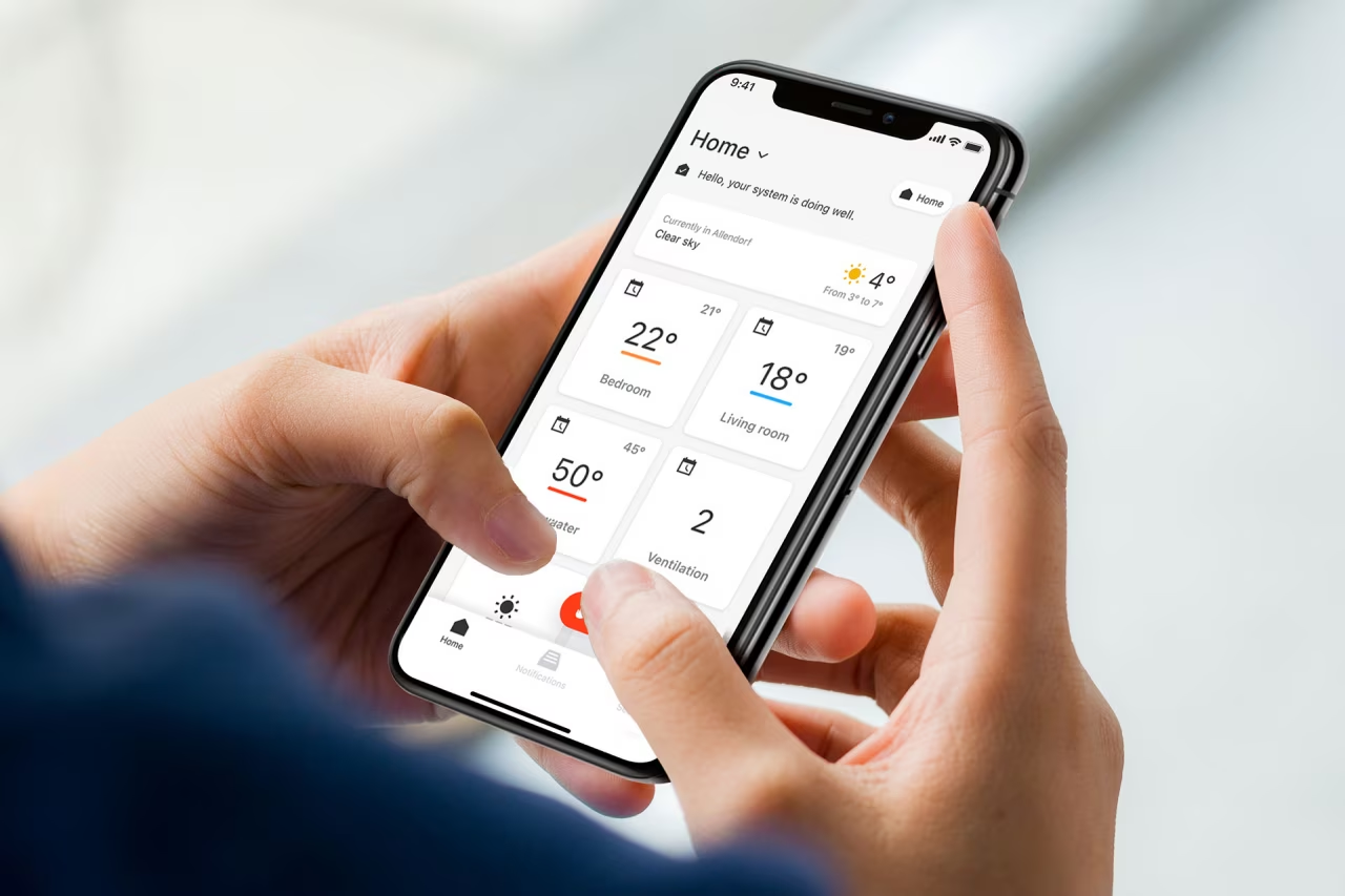
If you have any questions or need help troubleshooting, please contact your contractor. If your heating system is already connected to the ViCare app, you can forward the fault report to your contractor with one click. You can also ask your questions in the AHI Carrier Community .
Fault codes for wall-mounted gas boilers of the 200 and 300 series with the Vitotronic control unit
Note: Some measures include coding addresses or coding groups. Installation of these codes may only be performed by authorized contractors.
| Displayed fault code | System characteristics | Cause of malfunction | Cause of malfunction |
|---|---|---|---|
| 10 | Regulated as if the outside temperature was 0°C | Short circuit, outside temperature sensor | Check the outside temperature sensor |
| 18 | Regulated as if the outside temperature was 0°C | Broken wire, outside temperature sensor | Check the outside temperature sensor |
| 19 | Regulated as if the outside temperature was 0°C | Communication with the RF outdoor temperature sensor is interrupted (RF outdoor temperature sensor, KM-BUS to the wireless base station, wireless base station or wireless repeater is faulty or damaged) | Check the wireless connection (install the RF outdoor temperature sensor and wireless repeater close to the boiler). Check the KM-BUS to the wireless base station. Turn off the outdoor temperature sensor and wireless repeater, then turn them back on. Replace the RF outdoor temperature sensor. Replace the wireless repeater. Replace the wireless base station. |
| 20 | Regulates without flow temperature sensor (low-loss manifold) | Short circuit, flow temperature sensor in the system | Check the low loss collector sensor |
| 28 | Adjustable without flow temperature sensor (low-loss manifold) | Broken wire, flow temperature sensor in the system | Check the low-loss flow sensor. If the low-loss flow sensor is not connected, set the code to 52:0. |
| 30 | The burner is blocked | Short circuit, water temperature sensor in the boiler | Check the boiler water temperature sensors |
| 38 | The burner is blocked | Broken wire, water temperature sensor in the boiler | Check the boiler water temperature sensors |
| 40 | The mixer is closed | Short circuit, flow temperature sensor, heating circuit 2 (with mixer) | Check the flow temperature sensor |
| 44 | The mixer is closed | Short circuit, flow temperature sensor, heating circuit 3 (with mixer) | Check the flow temperature sensor |
| 48 | The mixer is closed | Short circuit, flow temperature sensor, heating circuit 2 (with mixer) | Check the flow temperature sensor |
| 50 | There is no DHW heating from the boiler | Short circuit, cylinder temperature sensor | Check the cylinder temperature sensor |
| 58 | No hot water heating | There is no DHW heating from the boiler | Check the cylinder temperature sensor |
| 90 | Normal operation | Normal operation | Check the sensor on the solar panel control module |
| 91 | Normal operation | Short circuit, temperature sensor | Check the sensor on the solar panel control module |
| 92 | No hot water heating from solar panels | Short circuit, manifold temperature sensor | Check the temperature sensor on the solar control module or the sensor on the Vitosolic |
| 93 | Normal operation | Short circuit, return manifold temperature sensor | Check the temperature sensor at connection S3 on the Vitosolic. |
| 94 | No hot water heating from solar panel | Short circuit, cylinder temperature sensor | Temperature sensor on the solar system control module |
| 98 | Normal operation | Broken wire, temperature sensor | Temperature sensor on the solar panel control module |
| 99 | Normal operation | Broken wire, temperature sensor | Check the sensor on the solar panel control module |
| 1A | The burner is blocked | Flow sensor 1, left (plug 163) is faulty | Replace the sensor |
| 1b | The burner is blocked | Flow sensor 2, right (plug 163A) is faulty | Replace the sensor |
| 1F | The burner is blocked | Too much difference in flow rate | Clean the heat exchanger by flushing |
| 4C | The mixer is closed | Wire break, flow temperature sensor, heating circuit 3 (with mixer) | Check the flow temperature sensor |
| 9A | No hot water heating from solar panel | Broken wire, manifold temperature sensor | Check the temperature sensor on the solar control module or the sensor on the Vitosolic. |
| 9b | Normal operation | Broken wire, return manifold temperature sensor | Check the temperature sensor at connection S3 on the Vitosolic. |
| 9C | No hot water heating from solar panel | Broken wire, cylinder temperature sensor | Check the temperature sensor on the solar control module or the sensor on the Vitosolic |
| 9E | Normal operation | There is no flow or the flow rate is too low in the solar circuit, or the temperature limiter has tripped. | Check the solar circuit pump and solar circuit. Confirm the fault message. |
| 9F | Normal operation | Solar control module or Vitosolic faulty | Replace the solar control module or Vitosolic |
| A3 | The burner is blocked | The flue gas temperature sensor is installed incorrectly | Install the flue gas temperature sensor correctly |
| A4 | Normal operation | Max. system pressure exceeded | Check the system pressure (maximum system pressure 6 bar). Check the operation and size of the membrane expansion tank. Bleed the heating system. |
| A7 | Normal operation in accordance with delivery conditions | The programming unit is faulty | Replace the programming unit |
| b0 | The burner is blocked | Short circuit, flue gas temperature sensor | Check the flue gas temperature sensor |
| b1 | Normal operation in accordance with delivery conditions | Communication error, programming block | Check the connections and replace the programming unit if necessary. |
| b5 | Normal operation in accordance with delivery conditions | Internal malfunction | Replace the control unit |
| b7 | The burner is blocked | Malfunction, boiler coding card | Connect the boiler coding card or replace it if it is faulty |
| b8 | The burner is blocked | Broken wire, flue gas temperature sensor | Check the flue gas temperature sensor |
| bA | The mixer regulates the flow temperature up to 20 °C | Communication error, expansion kit for heating circuit 2 (with mixer) | Check the connections and the expansion kit code |
| bb | The mixer regulates the flow temperature up to 20 °C | Communication error, expansion kit for heating circuit 3 (with mixer) | Check the connections and the expansion kit code |
| bC | Normal operation without remote control | Communication error, Vitotrol remote control, heating circuit 1 (without mixer) | Check the connections, cable, and coding address "A0" in the "Heating Circuit" group, as well as the DIP switch on the remote control. When using wireless remote controls: check the transmission path connections; place the remote control and wireless repeater close to the boiler. Check the KM-BUS connection to the wireless base station. Replace the wireless components. |
| bd | Normal operation without remote control | Communication error, Vitotrol remote control, heating circuit 2 (with mixer) | Check the connections, cable, and coding address "A0" in the "Heating Circuit" group, as well as the remote control settings. When using wireless remote controls: check the data path connections; place the remote control and wireless repeater close to the boiler. Check the KM-BUS connection to the wireless base station. Replace the wireless communication components. |
| bE | Normal operation without remote control | Communication error, Vitotrol remote control, heating circuit 3 (with mixer) | Check the connections, cable, and coding address "A0" in the "Heating Circuit" group, as well as the remote control settings. When using wireless remote controls: check the transmission path connections; position the remote control and wireless repeater close to the boiler. Check the KM-BUS connection to the wireless base station. Replace the wireless network components. |
| bF | Normal operation | Incorrect LON communication module | Replace the LON communication module |
| C1 | Normal operation | Communication error, extension EA1 | Check the connections |
| C2 | Normal operation | Communication error, solar control module or Vitosolic | Check the solar panel control module or Vitosolic |
| C3 | Normal operation | Communication error, extension AM1 | Check the connections |
| C4 | Normal operation | Communication error, OpenTherm extension | Check out the OpenTherm extension |
| C5 | Normal operation, max. pump speed | Communication error, variable speed pump | Check the KM-BUS pump |
| CD | Normal operation | Communication error, Vitocom 100 (KM-BUS) | Check connections, Vitocom 100 and coding address "95" in the "General"/1 group |
| CF | Normal operation | Communication error, LON communication module | Replace the LON communication module |
| d6 | Normal operation | Input DE1 on expander EA1 reports a fault | Please troubleshoot the device in question. |
| d7 | Normal operation | Input DE2 on expansion EA1 reports a fault | Troubleshooting the relevant device |
| d8 | Normal operation | Input DE3 on expansion EA1 reports a fault | Troubleshooting the relevant device |
| dA | Normal operation without room influence | Short circuit, room temperature sensor, heating circuit 1 (without mixer) | Check the room temperature sensor, heating circuit 1 |
| db | Normal operation without room influence | Short circuit, room temperature sensor, heating circuit 2 (with mixer) | Check the room temperature sensor, heating circuit 2 |
| dC | Normal operation without room influence | Short circuit, room temperature sensor, heating circuit 3 (with mixer) | Check the room temperature sensor, heating circuit 3 |
| dd | Normal operation without room influence | Wire break, room temperature sensor, heating circuit 1 (without mixer) | Check the room temperature sensor, heating circuit 1 and remote control settings. |
| dE | Normal operation without room influence | Wire break, room temperature sensor, heating circuit 2 (with mixer) | Check the room temperature sensor, heating circuit 2 and remote control settings |
| dF | Normal operation without room influence | Wire break, room temperature sensor, heating circuit 3 (with mixer) | Check the room temperature sensor, heating circuit 3 and remote control settings. |
| E0 | Normal operation | External LON subscriber failure | Check LON connections and subscribers |
| E3 | The burner is in an emergency condition | Heat output too low during calibration. Temperature limiter tripped. | Ensure adequate heat transfer. Press the reset button R |
| E4 | The burner is blocked | Malfunction, supply voltage 24 V | Replace the control unit |
| E5 | The burner is blocked | Flame amplifier malfunction | Replace the control unit |
| Eb | The burner is faulty | Repeated loss of flame during calibration | Check the gap between the ionization electrode and the burner gauze assembly. Check the gas type. Check the flue system; eliminate flue gas recirculation if necessary. Press the reset button R. |
| EC | The burner is in a faulty state | Parameter error during calibration | Press the reset button R or replace the boiler coding card and then press the reset button R |
| Ed | The burner is in a faulty state | Internal malfunction | Replace the control unit |
| F0 | The burner is blocked | Internal malfunction | Replace the control unit |
| F1 | The burner is in an emergency condition | The flue gas temperature has exceeded the limit | Check the heating system's fill level. Bleed the system. Press the reset button R after the flue system has cooled. |
| F2 | The burner is in a faulty state Check the heating system fill level. | The water temperature sensor in the boiler has been triggered | Check the circulation pump. Bleed the system. Check the boiler water temperature sensor and connecting cables. Press the reset button R. |
| F6 | The burner is in a faulty state | The temperature values of the boiler water temperature sensors differ too much from each other | Replace boiler water temperature sensors |
| F8 | The burner is faulty | The fuel valve closes late | Check the gas solenoid valve. Check both control paths. Press the reset button R |
| FF | The burner is blocked or in a fault condition | Internal fault or reset button R is blocked | Restart the device. Replace the control unit if the device does not restart. |